SINOTIMER MC901-611
SINOTIMER MC901-611 Universal Intelligent Temperature Control Meter User Manual
Merk: SINOTIMER
Model: MC901-611
1. Inleiding
The SINOTIMER MC901-611 is a universal intelligent temperature control meter designed for precise temperature regulation in various industrial and laboratory applications. This device features a clear LCD display, multiple input types, and reliable output options, making it suitable for a wide range of temperature control needs. This manual provides essential information for the safe and effective operation, installation, and maintenance of your MC901-611 temperature controller.
2. Veiligheidsinformatie
Please read this manual thoroughly before operating the device to ensure safe and correct usage. Keep this manual for future reference.
Algemene veiligheidsmaatregelen:
- Zorg ervoor dat de voeding voltage matches the specifications of the device (100-240V AC, 50/60Hz).
- Do not operate the device in environments with excessive dust, humidity, corrosive gases, or strong vibrations.
- Disconnect power before performing any wiring, maintenance, or inspection.
- Installatie en bedrading mogen uitsluitend worden uitgevoerd door gekwalificeerd personeel.
- Avoid touching internal components when the device is powered on.
- Zorg voor een goede aarding om elektrische schokken te voorkomen.
- Demonteer of wijzig het apparaat niet. Ongeautoriseerde wijzigingen kunnen de garantie ongeldig maken en veiligheidsrisico's met zich meebrengen.
3. Product voorbijview
The MC901-611 temperature controller features a compact design with a clear digital display and intuitive control buttons.

Afbeelding 3.1: Voorpaneel
This image displays the front panel of the MC901-611. It features two digital displays: PV (Process Value) in red, showing the current temperature, and SV (Set Value) in green, showing the target temperature. Below the displays are indicator lights for OUT (Output), AT (Auto-tuning), ALM1 (Alarm 1), and ALM2 (Alarm 2). The control buttons include SET, R/S (Run/Stop), Down arrow, and Up arrow.
Belangrijkste componenten:
- PV-weergave: Shows the current measured temperature (Process Value).
- SV-weergave: Shows the set target temperature (Set Value).
- Indicatielampjes: OUT (Output status), AT (Auto-tuning status), ALM1 (Alarm 1 status), ALM2 (Alarm 2 status).
- Bedieningsknoppen: SET (Enter/Confirm settings), R/S (Run/Stop), Up/Down arrows (Adjust values).
- Eindblok: Located at the rear for electrical connections.
- Montagebeugels: For secure panel installation.

Figure 3.2: Side Panel with Specifications Label
This image shows the side of the MC901-611, highlighting the product label. The label provides crucial information such as Model (MC901-611), Input type (K, default setting), Temperature Range (0-1300°C), Temperature Unit (Celsius/Fahrenheit), Output type (Relay/SSR), Alarm (ALM1), Accuracy Class (0.5), and Power Supply (100-240V AC, 50/60Hz).
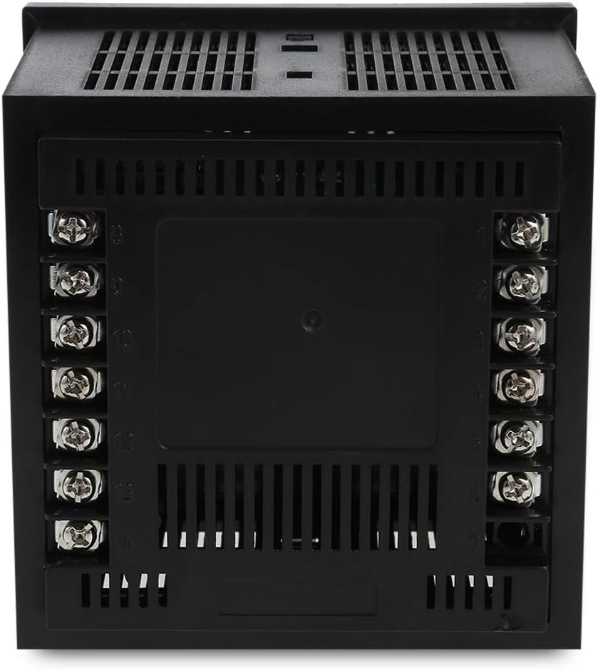
Figure 3.3: Rear Panel with Terminal Block
This image displays the rear of the MC901-611, featuring the terminal block for electrical connections. The terminals are clearly numbered, indicating where to connect power, sensor inputs, and control outputs. Proper wiring according to the provided diagram is essential for safe and correct operation.
4. Installatie en installatie
4.1 Panel Mounting:
The MC901-611 is designed for panel mounting. Ensure the cutout dimensions in your panel match the device's specifications.
- Cut an opening in your panel according to the specified dimensions (refer to specifications section for exact size).
- Insert the MC901-611 into the panel cutout from the front.
- Attach the provided mounting brackets to the sides of the controller from the rear of the panel.
- Tighten the screws on the mounting brackets to secure the controller firmly in place. Do not overtighten.

Figuur 4.1: Montagebeugels
This image shows the two mounting brackets included with the MC901-611. These brackets are used to secure the temperature controller firmly within a panel cutout, ensuring stable installation.
4.2 Bedradingsschema:
Refer to the wiring diagram on the side of the unit or in the detailed manual for correct connections. Ensure all connections are secure and insulated.
- Voeding: Connect the main power supply (100-240V AC, 50/60Hz) to the designated terminals.
- Sensoringang: Connect your temperature sensor (e.g., K-type thermocouple) to the sensor input terminals. Ensure correct polarity for thermocouples.
- Besturingsuitgang: Connect your heating/cooling element or SSR to the control output terminals.
- Alarm Output (Optional): If using alarm functions, connect external alarm devices to the alarm output terminals.
Note: A detailed wiring diagram is typically provided on the physical unit or in a separate wiring guide. Always consult the specific diagram for your model.
5. Gebruiksaanwijzing
5.1 Inschakelen:
Once wired correctly, apply power to the unit. The PV display will show the current temperature, and the SV display will show the last set temperature.
5.2 Setting the Target Temperature (SV):
- Druk op de SET Druk één keer op de knop. Het SV-display begint te knipperen.
- Gebruik de Up (▲) En Omlaag (▼) arrow buttons to adjust the target temperature.
- Druk op de SET button again to confirm the new SV and exit the setting mode. The SV display will stop flashing.
5.3 Parameterinstellingen:
To access advanced parameter settings (e.g., input type, control mode, alarm settings):
- Houd de SET button for approximately 3-5 seconds until the first parameter code appears on the PV display.
- Gebruik de Up (▲) En Omlaag (▼) arrow buttons to navigate through different parameter codes.
- Pers SET naar view the value of the currently displayed parameter.
- Gebruik de Up (▲) En Omlaag (▼) arrow buttons to change the parameter value.
- Pers SET to confirm the new value and return to the parameter code display.
- Om de parameterinstelmodus te verlaten, houdt u de knop ingedrukt. SET button again for 3-5 seconds, or wait for the device to automatically exit after a period of inactivity.
Consult the full product manual for a complete list of parameter codes and their functions.
5.4 Auto-tuning (AT):
Auto-tuning helps the controller optimize its PID parameters for stable and accurate temperature control. This process is recommended after initial setup or if control performance is unsatisfactory.
- Set the desired target temperature (SV).
- Houd de R/S button for approximately 3-5 seconds. The AT indicator light will illuminate, and the controller will begin the auto-tuning process.
- Allow the auto-tuning process to complete. This may take some time as the controller cycles the output to learn the system's characteristics. The AT light will turn off once tuning is complete.
- Do not interrupt the auto-tuning process.
6. Onderhoud
Regular maintenance ensures the longevity and optimal performance of your MC901-611 temperature controller.
- Schoonmaak: Disconnect power before cleaning. Use a soft, dry cloth to wipe the surface of the unit. Do not use abrasive cleaners, solvents, or water, as these can damage the display or internal components.
- Inspectie: Periodically check all wiring connections for looseness or damage. Ensure the terminal screws are tight.
- Omgeving: Zorg ervoor dat de werkomgeving binnen de opgegeven temperatuur- en vochtigheidsbereiken blijft om schade te voorkomen.
- Sensorcontrole: If temperature readings appear inaccurate, check the sensor and its wiring for damage or corrosion.
7. Probleemoplossing
This section addresses common issues you might encounter with your MC901-611 temperature controller.
| Probleem | Mogelijke oorzaak | Oplossing |
|---|---|---|
| Geen beeld/Uitgeschakeld | Geen stroomvoorziening; Losse bedrading; Doorgebrande zekering. | Check power connection; Verify wiring; Replace fuse if necessary (by qualified personnel). |
| PV display shows "HHHH" or "LLLL" | Sensor open circuit (HHHH); Sensor short circuit or reverse connection (LLLL); Sensor type mismatch. | Check sensor wiring and connections; Ensure correct sensor type is selected in parameters. |
| Temperature not controlled accurately | Incorrect PID parameters; Sensor not properly installed; Load capacity mismatch. | Perform auto-tuning; Ensure sensor is in good thermal contact with the process; Verify output capacity matches load. |
| Output indicator (OUT) not lighting up | SV is equal to PV (no control action needed); Output wiring issue; Internal fault. | Check SV and PV values; Inspect output wiring; If problem persists, contact support. |
Als het probleem blijft bestaan nadat u deze oplossingen hebt geprobeerd, neem dan contact op met de klantenservice.
8. Specificaties
Technical specifications for the SINOTIMER MC901-611 Universal Intelligent Temperature Control Meter.
| Functie | Specificatie |
|---|---|
| Model | MC901-611 |
| Invoertype | K (default setting), Universal Input |
| Temperatuurbereik | 0-1300°C (depending on sensor type) |
| Temperatuureenheid | Celsius/Fahrenheit selectable |
| Uitvoertype | Relais/SSR |
| Alarm | ALM1 |
| Nauwkeurigheidsklasse | 0.5 |
| Stroomvoorziening | 100-240V wisselstroom, 50/60Hz |
| Weergavetype | LCD |
| Artikelgewicht | 8.8 ons |
| Pakket afmetingen | 4.3 x 4.3 x 3.6 inch |
9. Garantie en ondersteuning
Garantie-informatie:
SINOTIMER products are typically covered by a limited warranty against defects in materials and workmanship. Please refer to the warranty card included with your product or contact SINOTIMER customer service for specific warranty terms and conditions.
Klantenservice:
For technical assistance, troubleshooting beyond this manual, or warranty claims, please contact SINOTIMER customer support. Have your product model number (MC901-611) and purchase information ready when contacting support.
Contact information for SINOTIMER can usually be found on their official webwebsite of op de productverpakking.