1. Inleiding
The Yaxun YX-9205 Digital Multimeter is a versatile and reliable instrument designed for measuring various electrical parameters. It is suitable for professional electricians, hobbyists, and students for testing and troubleshooting electronic circuits and devices. This manual provides essential information for safe and effective operation of your multimeter.
2. Veiligheidsinformatie
Always observe safety precautions when using any electrical testing equipment. Failure to do so may result in injury or damage to the multimeter or the equipment under test.
- Zorg ervoor dat de multimeter goed werkt voordat u hem gebruikt.
- Niet toepassen voltage of stroom die de maximaal gespecificeerde limieten voor elk bereik overschrijdt.
- Koppel de testkabels altijd los van het circuit voordat u functies of bereiken wijzigt.
- Wees voorzichtig bij het werken met voltagboven 30V AC RMS, 42V piek of 60V DC, aangezien deze een schokgevaar opleveren.
- Vervang de batterij wanneer de batterij-indicator oplicht om nauwkeurige metingen te garanderen.
- Gebruik de multimeter niet in explosiegevaarlijke omgevingen of in de aanwezigheid van brandbare gassen of stof.
- Keep fingers behind the probe barriers during measurements.
3. Producteigenschappen
The Yaxun YX-9205 Digital Multimeter offers a range of functions and features for comprehensive electrical testing:
- Multi-scale measurements for various electrical parameters.
- Meet gelijkspanningtage, AC voltage, DC Current, AC Current, Resistance, Capacitance, Diode, and Continuity.
- Transistor hFE gain test function.
- Large LCD display with 4 digits, maximum reading 1999.
- Data Hold function to freeze displayed values.
- Automatische uitschakelfunctie om de batterijduur te verlengen.
- Audible continuity signal.
- Indicator voor lage batterij.
- Integrated kickstand for convenient viewind.
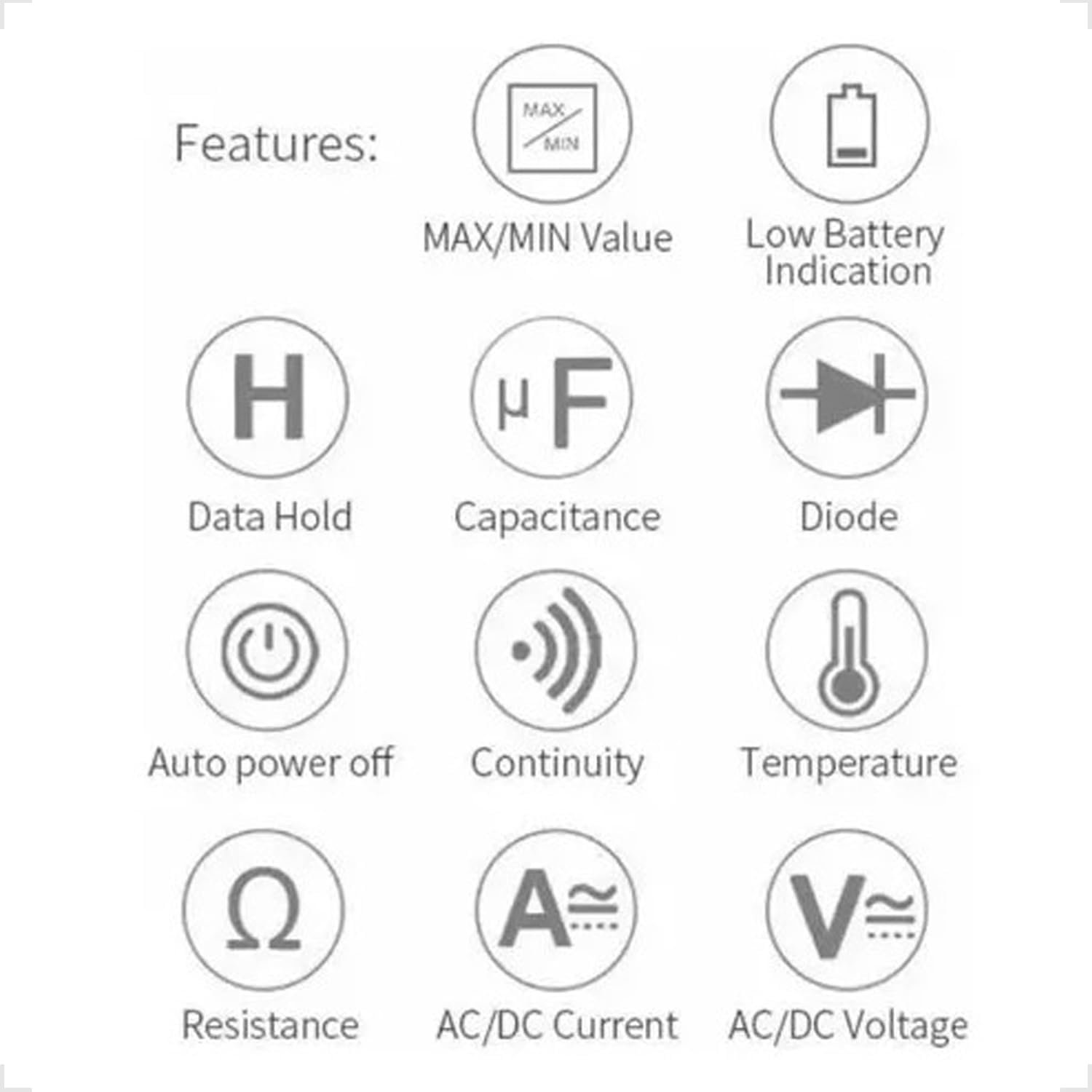
Figure 3.1: Feature Icons. This image displays a set of icons illustrating the key functions and capabilities of the Yaxun YX-9205 Digital Multimeter, such as data hold, capacitance measurement, diode testing, and auto power off.
4. Inhoud van het pakket
Controleer of alle artikelen in uw pakket aanwezig zijn:
- Yaxun YX-9205 Digital Multimeter
- Testkabels (rood en zwart)
- 9V Battery (6F22 type)
- Temperature Probe (K-type thermocouple, if included)
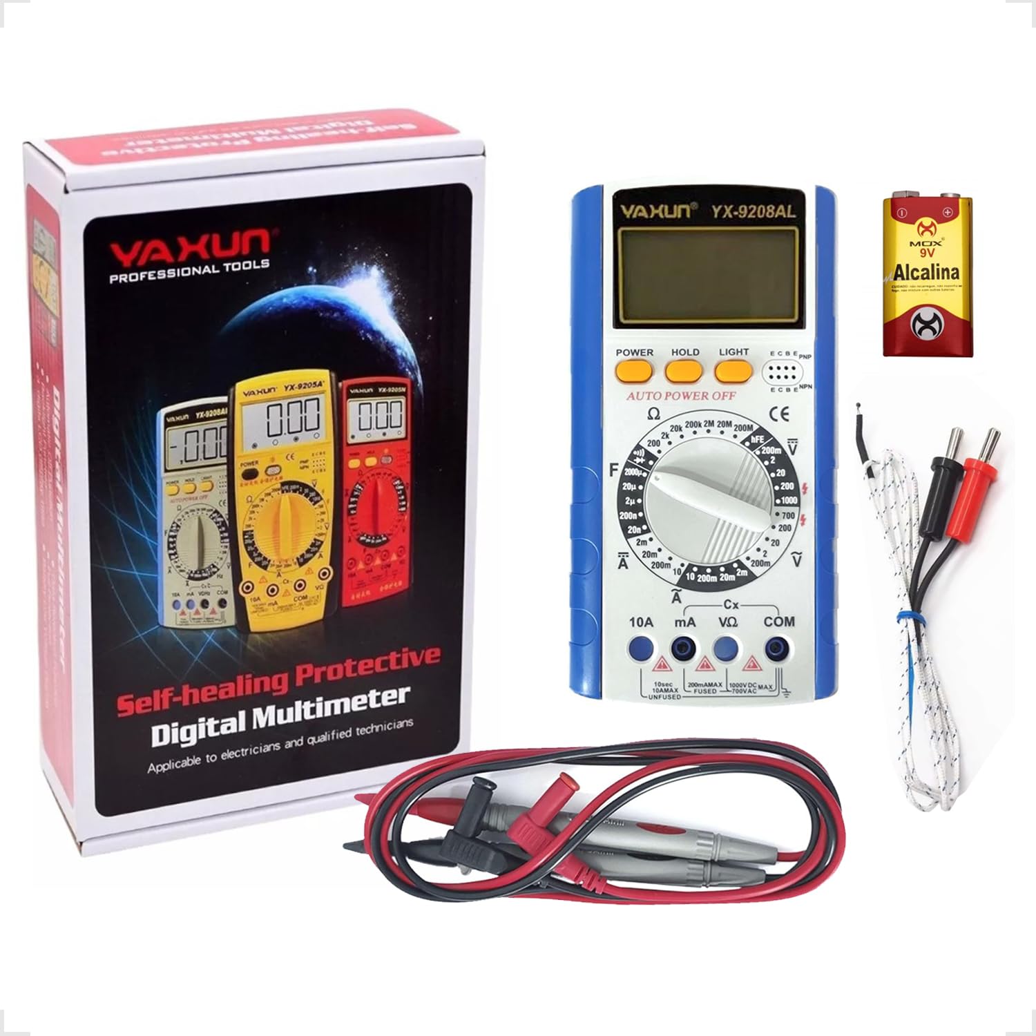
Figure 4.1: Package Contents. This image shows the Yaxun YX-9205 Digital Multimeter, along with its included red and black test leads and a 9V battery.
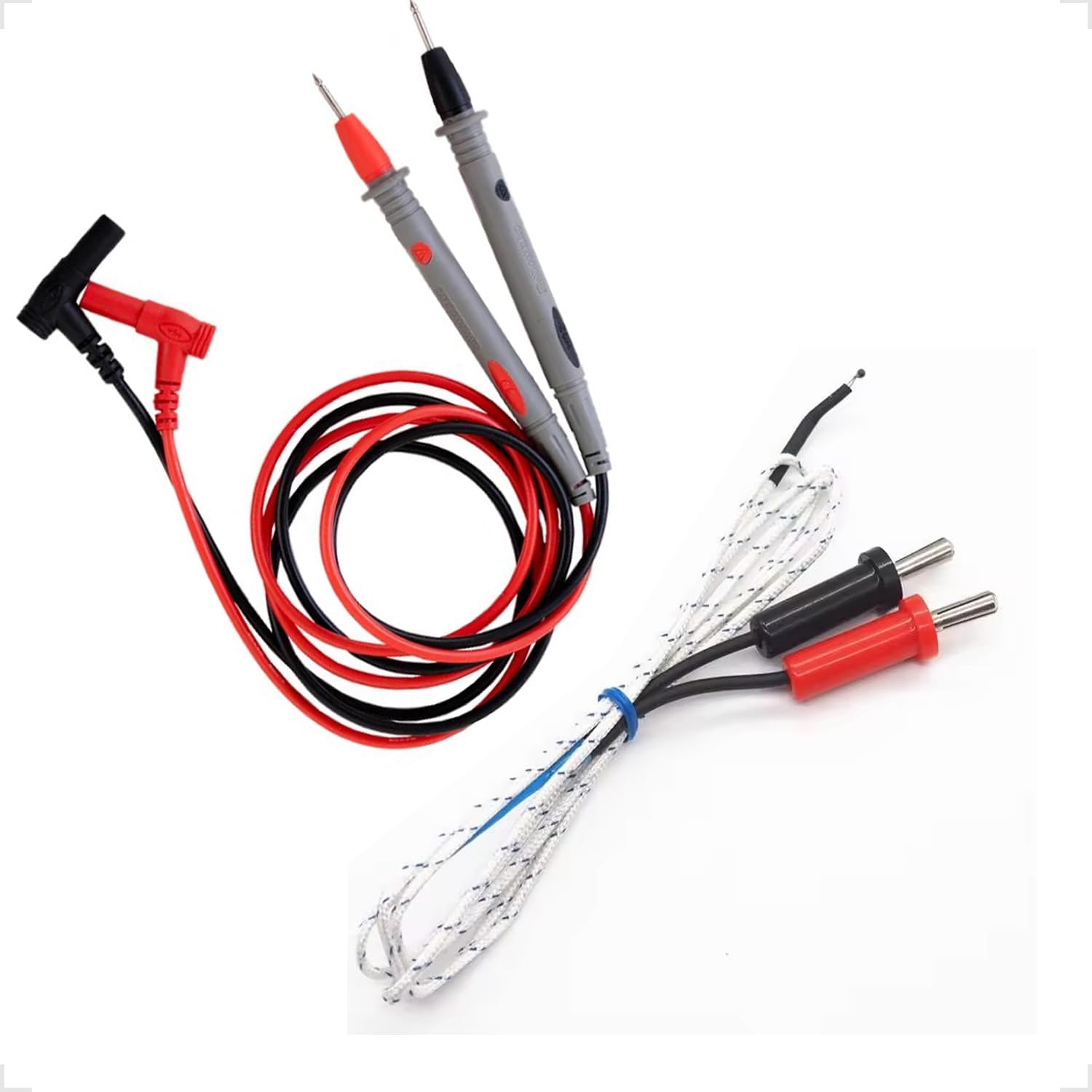
Figure 4.2: Test Leads and Temperature Probe. This image details the included red and black test leads, essential for making electrical measurements, and a white temperature probe.
5. Instellen
5.1 Batterij installatie
The multimeter requires a 9V battery for operation. Follow these steps to install or replace the battery:
- Zorg ervoor dat de multimeter is uitgeschakeld en dat de meetsnoeren zijn losgekoppeld.
- Zoek het klepje van het batterijcompartiment aan de achterkant van de multimeter.
- Use a screwdriver to remove the screw securing the cover, then lift the cover off.
- Sluit de 9V-batterij aan op de batterijclip en let daarbij op de juiste polariteit.
- Plaats de batterij in het compartiment en sluit het deksel weer af met de schroef.

Figure 5.1: Battery Compartment. This image shows the rear of the multimeter, highlighting the battery compartment cover, which needs to be opened for battery installation or replacement.
5.2 Testkabels aansluiten
Een correcte aansluiting van de meetsnoeren is cruciaal voor nauwkeurige en veilige metingen:
- Steek de zwarte meetsnoer in de "COM" (Common) aansluiting.
- Voor de meeste voltage, resistance, and continuity measurements, insert the red test lead into the "VΩmA" jack.
- For high current measurements (up to 10A), insert the red test lead into the "10A" jack. Ensure the rotary switch is set to the appropriate current range.
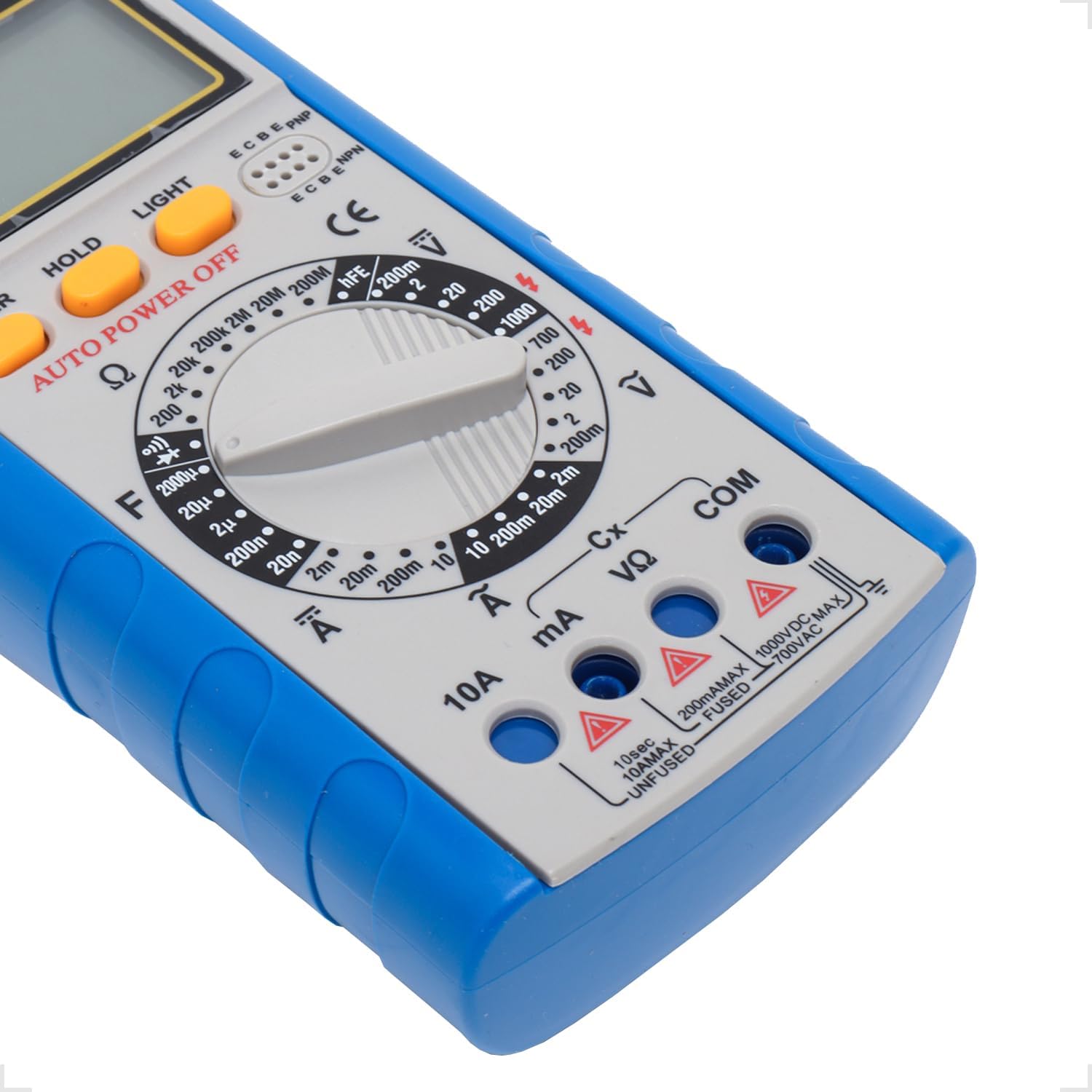
Figure 5.2: Input Jacks. This image provides a detailed view of the multimeter's input jacks: COM (common), VΩmA (for voltage, resistance, and low current), and 10A (for high current measurements).
5.3 Gebruik van de standaard
The multimeter features a built-in kickstand for hands-free operation and improved viewing angle. Simply pull out the kickstand from the back of the unit to deploy it.

Figure 5.3: Multimeter with Kickstand. This image shows the multimeter standing upright with its integrated kickstand extended, providing a stable and convenient viewhoek tijdens gebruik.
6. Gebruiksaanwijzing
6.1 Algemene werking
The YX-9205 multimeter is operated primarily using the rotary switch and function buttons.
- Draaischakelaar: Selects the desired measurement function (e.g., VDC, VAC, ADC, AAC, Ω, F, Diode, Continuity, hFE).
- Aanknop: Hiermee schakel je de multimeter in of uit.
- Pauzeknop: Bevriest de huidige waarde op het display. Druk nogmaals om de vergrendeling op te heffen.
- LIGHT-knop: Activates the display backlight for better visibility in low-light conditions.

Figuur 6.1: Bedieningspaneel. Deze afbeelding geeft een gedetailleerd overzicht view of the multimeter's main controls, including the central rotary switch for function selection and the Power, Hold, and Light buttons.
6.2 DC-volume metentage (VDC)
- Insert the black lead into the COM jack and the red lead into the VΩmA jack.
- Draai de draaischakelaar naar de gewenste DC-spanning.tage bereik (bijv. 200mV, 2V, 20V, 200V, 1000V). Als het volumetagAls e onbekend is, begin dan met het hoogste bereik en verlaag dit indien nodig.
- Sluit de testprobes aan op het te meten onderdeel of circuit en let daarbij op de polariteit.
- Lees het deeltage-waarde op het LCD-scherm.
6.3 AC-volume metentage (VAC)
- Insert the black lead into the COM jack and the red lead into the VΩmA jack.
- Draai de draaischakelaar naar het gewenste wisselstroomvolume.tage bereik (bijv. 200mV, 2V, 20V, 200V, 700V). Als het volumetage is unknown, start with the highest range.
- Sluit de testprobes aan op het te meten onderdeel of circuit. De polariteit is niet cruciaal voor wisselstroommetingen.tage.
- Lees het deeltage-waarde op het LCD-scherm.
6.4 Measuring DC Current (ADC)
Caution: Always connect the multimeter in series with the circuit when measuring current. Never connect it in parallel across a voltage-bron, aangezien dit de multimeter en het circuit kan beschadigen.
- Determine the expected current. For currents up to 200mA, use the VΩmA jack for the red lead. For currents up to 10A, use the 10A jack for the red lead. The black lead always goes into COM.
- Turn the rotary switch to the appropriate DC Current range (e.g., 2mA, 20mA, 200mA, 10A).
- Open the circuit where current is to be measured and connect the test leads in series.
- Lees de huidige waarde af op het LCD-scherm.
6.5 Measuring AC Current (AAC)
Caution: Always connect the multimeter in series with the circuit when measuring current. Never connect it in parallel across a voltage-bron, aangezien dit de multimeter en het circuit kan beschadigen.
- Determine the expected current. For currents up to 200mA, use the VΩmA jack for the red lead. For currents up to 10A, use the 10A jack for the red lead. The black lead always goes into COM.
- Turn the rotary switch to the appropriate AC Current range (e.g., 2mA, 20mA, 200mA, 10A).
- Open the circuit where current is to be measured and connect the test leads in series.
- Lees de huidige waarde af op het LCD-scherm.
6.6 Weerstand meten (Ω)
Caution: Ensure the circuit or component under test is completely de-energized before measuring resistance. Disconnect power and discharge any capacitors.
- Insert the black lead into the COM jack and the red lead into the VΩmA jack.
- Turn the rotary switch to the desired Resistance range (e.g., 200Ω, 2kΩ, 20kΩ, 200kΩ, 2MΩ, 20MΩ, 200MΩ).
- Sluit de testprobes aan op het te meten onderdeel.
- Lees de weerstandswaarde af op het lcd-scherm.
6.7 Capaciteit meten (F)
Caution: Ensure capacitors are fully discharged before testing. High voltage capacitors can store dangerous charges.
- Insert the black lead into the COM jack and the red lead into the VΩmA jack.
- Turn the rotary switch to the Capacitance (F) function and select the appropriate range (e.g., 20nF, 200nF, 2µF, 20µF, 200µF).
- Sluit de testprobes aan op de aansluitingen van de condensator.
- Lees de capaciteitswaarde af op het LCD-display.
6.8 Diodetest
- Insert the black lead into the COM jack and the red lead into the VΩmA jack.
- Turn the rotary switch to the Diode symbol.
- Sluit de rode meetpen aan op de anode en de zwarte meetpen op de kathode van de diode. Op het display wordt het voorwaartse volume weergegeven.tage-val (doorgaans 0.5V tot 0.8V voor siliciumdiodes).
- Reverse the probes. The display should show 'OL' (Open Loop) for a good diode. A reading in both directions or 'OL' in both directions indicates a faulty diode.
6.9 Continuïteitstest
- Insert the black lead into the COM jack and the red lead into the VΩmA jack.
- Turn the rotary switch to the Continuity symbol (often shared with the Diode function).
- Sluit de testprobes aan over het circuit of het onderdeel.
- If the resistance is below approximately 50Ω, the buzzer will sound, indicating continuity. The display will also show the resistance value.
6.10 Transistor hFE-test
- Draai de draaischakelaar naar de hFE-stand.
- Bepaal of de transistor een NPN- of een PNP-transistor is.
- Insert the transistor's emitter, base, and collector leads into the corresponding holes in the hFE socket on the multimeter.
- Read the hFE (DC current gain) value on the LCD display.
7. Specificaties
| Parameter | Bereik | Nauwkeurigheid |
|---|---|---|
| DC voltage | 200mV, 2V, 20V, 200V, 1000V | ±(0.5% + 1 cijfers) |
| AC voltage | 200mV, 2V, 20V, 200V, 700V | ±(0.8% + 3 cijfers) |
| DC-stroom | 2mA, 20mA, 200mA, 10A | ±(0.5% + 1 cijfers) |
| AC stroom | 2mA, 20mA, 200mA, 10A | ±(1.0% + 3 cijfers) |
| Weerstand | 200Ω, 2kΩ, 20kΩ, 200kΩ, 2MΩ, 20MΩ, 200MΩ | ±(0.8% + 1 cijfers) |
| Capaciteit | 20nF, 200nF, 2µF, 20µF, 200µF | ±(4.0% + 3 cijfers) |
| Weergave | 1999 counts, 60 x 31.5mm LCD | |
| Stroomvoorziening | 9V-batterij (6F22) | |
| Afmetingen (L x B x H) | 180x86x35mm | |
8. Onderhoud
8.1 Reinigen
Om de multimeter schoon te maken, veegt u de behuizing schoon met een doekje.amp cloth and a mild detergent. Do not use abrasives or solvents. Ensure the multimeter is completely dry before use.
8.2 Batterij vervangen
When the low battery indicator appears on the display, replace the 9V battery as described in the 'Battery Installation' section (5.1). A weak battery can lead to inaccurate readings.
8.3 Zekering vervangen
Caution: Always disconnect test leads and turn off the multimeter before replacing the fuse. Use only fuses of the specified type and rating.
If the multimeter fails to measure current, the fuse may be blown. To replace the fuse:
- Schakel de multimeter uit en koppel alle meetsnoeren los.
- Open the battery compartment cover as described in section 5.1.
- Verwijder voorzichtig de oude zekering.
- Install a new fuse of the correct type and rating (e.g., F200mA/250V for mA ranges, F10A/250V for 10A range). Refer to the markings near the fuse holder if available.
- Plaats het deksel van het batterijcompartiment terug en zet het vast met de schroef.
9. Probleemoplossing
| Probleem | Mogelijke oorzaak | Oplossing |
|---|---|---|
| Geen weergave of zwak display | Lege of zwakke batterij | Vervang de 9V-batterij. |
| Onjuiste metingen | Incorrect range selected, poor lead connection, weak battery | Select the correct range, ensure leads are firmly connected, replace battery. |
| Geen actuele meting | Blown fuse, incorrect lead connection | Check and replace fuse if necessary, ensure leads are in correct current jacks and connected in series. |
| 'OL' (Overload) wordt weergegeven | Measurement exceeds selected range, open circuit | Select a higher range, check for open circuit. |
10. Garantie en ondersteuning
This Yaxun YX-9205 Digital Multimeter is designed for reliability and performance. For specific warranty information, please refer to the purchase documentation or contact your retailer. For technical support or inquiries, please reach out to the Yaxun customer service department or your local distributor.